Definition
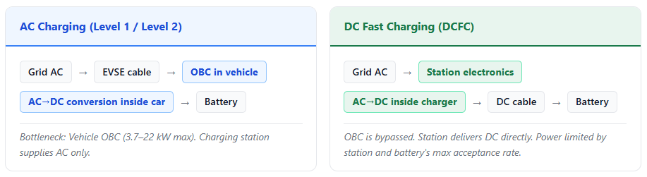
DC fast charging (DCFC) is a method of electric vehicle charging that delivers high-power direct current directly to the vehicle’s battery pack, bypassing the vehicle’s onboard charger (OBC). Unlike AC charging — where the vehicle’s OBC converts grid AC to battery DC — DCFC places the power conversion electronics inside the charging station itself. This allows the station to supply DC at voltages and currents matched to the battery pack (typically 400–1,000 V DC), at power levels ranging from 25 kW to 500+ kW. The result: a 60 kWh battery can reach 80% charge in 15–45 minutes instead of the 4–10 hours required by Level 2 AC.
On This Page
Nomenclature by Region
The terminology for DC fast charging is not globally uniform. The underlying technology is the same, but different standards bodies and markets use distinct naming conventions.
| Region / Standard | Term Used | Governing Standard |
|---|---|---|
| North America | “Level 3 charging” | SAE J1772 (connector); IEC 61851-23 (system) |
| Europe / International | “Mode 4 charging” | IEC 61851-23 and IEC 61851-24 — Mode 4 defines DC charging using off-board chargers[1] |
| China | “GB/T DC charging” | GB/T 20234.3 — China’s national DC fast charging standard |
| Japan | “CHAdeMO DC charging” | CHAdeMO protocol; transitioning toward ChaoJi |
“Level 3” is a North American informal convention — it does not appear in IEC standards. The IEC framework uses Modes 1–4. Mode 4 specifically refers to DC charging where conversion occurs outside the vehicle (i.e., in the EVSE). All DC fast charging is Mode 4; not all Mode 4 is “Level 3” (a term meaningless outside North America).
Technical Principles
Why DC Fast Charging Is Faster: The OBC Bypass
The onboard charger (OBC) in most EVs converts AC to DC for the battery. OBCs are constrained in size, weight, and heat dissipation — they typically range from 3.7 kW to 22 kW. DC fast chargers relocate this conversion hardware to the station, where size and cooling are not constrained by the vehicle. A DC fast charging station’s power electronics can be the size of a refrigerator or a shipping container — allowing power levels 10–100× greater than any OBC.
Communication Protocol
DC fast charging requires real-time bidirectional communication between station and vehicle. This is not needed for AC charging, where the OBC manages all internal conversions. For DCFC, the station must know — at all times — the battery’s maximum safe voltage, current limits, state of charge, and temperature.
| Protocol | Used By | Capabilities |
|---|---|---|
| ISO 15118-2 | CCS (CCS1/CCS2), NACS/J3400 | Plug & Charge authentication, power negotiation, V2G basic support; required by NEVI program[2] |
| ISO 15118-20 | CCS, NACS/J3400 (emerging), ChaoJi | Full V2G bidirectional control, dynamic tariff communication, wireless charging support[2] |
| DIN SPEC 70121 | CCS (legacy, pre-ISO 15118) | Basic DC charging communication; precursor to ISO 15118; still used in many deployed vehicles and stations |
| CHAdeMO protocol (CAN bus) | CHAdeMO connectors only | Power negotiation, V2G; native bidirectional support from version 1.x; proprietary to CHAdeMO ecosystem[3] |
| GB/T 27930 | GB/T DC (China) | CAN bus-based; China-specific; ChaoJi introduces new signaling aligned with CHAdeMO 3.0 / GB/T |
The communication manages: maximum allowable voltage and current; battery temperature monitoring; safety interlocks (connector lock, ground fault, isolation monitoring); and — in systems supporting ISO 15118 — authentication, billing, and V2G energy dispatch.
Power Levels & Classification
There is no single industry-standard taxonomy for DC fast charging power classes — different bodies and publications use different labels. The table below reflects common industry usage, not a binding standard.
| Power Range | Common Label | Typical Application | ~Time to 80% (60 kWh battery) |
|---|---|---|---|
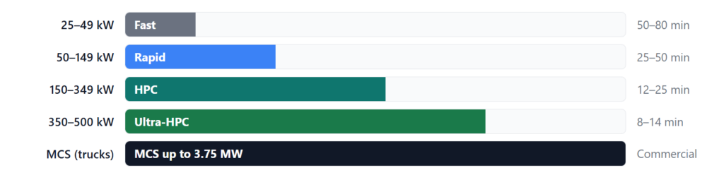
| 25–49 kW | Fast charging | Urban public stations, fleet depot support | 50–80 min |
| 50–149 kW | Rapid charging | Retail destinations, urban corridors, older highway sites | 25–50 min |
| 150–349 kW | High-Power Charging (HPC) | Highway corridors, major interchanges; CharIN HPC classification | 12–25 min |
| 350–500 kW | Ultra-High-Power / Extreme Fast | Next-gen highway hubs; 800V vehicle architectures (Porsche Taycan, Hyundai Ioniq 6, Lucid Air) | 8–14 min |
| 500 kW – 3.75 MW | Megawatt Charging (MCS) | Heavy commercial vehicles: Class 8 trucks, buses, mining equipment; CharIN MCS standard (3,000A × 1,250V)[4] | Commercial vehicle dependent |

DC Fast Charging vs. AC Charging
| Parameter | AC Level 2 Charging | DC Fast Charging |
|---|---|---|
| Power range | 3.7–22 kW | 25–500+ kW |
| Voltage delivered to vehicle | 120–240 V AC | 200–1,000 V DC |
| Current | 16–80 A (AC) | 50–500 A (DC) |
| AC→DC conversion location | Inside vehicle (OBC) | Inside charging station |
| Time to 80% (60 kWh battery) | 4–10 hours | 15–45 minutes |
| Typical installation location | Home, workplace, hotel, retail destination | Highway corridors, transit hubs, fleet depots |
| Hardware cost (approx.) | $500–$7,000 per unit | $20,000–$150,000+ per unit (excl. installation) |
| Grid requirement | Single-phase 120/240V; standard panel | 3-phase power; transformer upgrade often required |
| Battery degradation risk | Lower C-rate; minimal degradation impact | Higher C-rate; some accelerated degradation with frequent use (especially at high SoC) |
| V2G capability | Possible (typically 3.7–11 kW bidirectional) | Possible (up to 350+ kW bidirectional with compatible hardware) |
| Primary use case | Overnight charging; long dwell time | En-route top-up; short stops |
The relationship between DC fast charging and battery degradation is nuanced and chemistry-dependent. LFP batteries are significantly less sensitive to high C-rate charging than NMC. Infrequent DCFC use (highway travel) has minimal measurable impact on battery longevity for most modern EVs. Sustained, daily DCFC at high state of charge (above 80%) and high temperatures does accelerate degradation in NMC batteries. Most modern BMS systems actively manage this by throttling charge rate at high SoC and temperature extremes.
Connector Standards
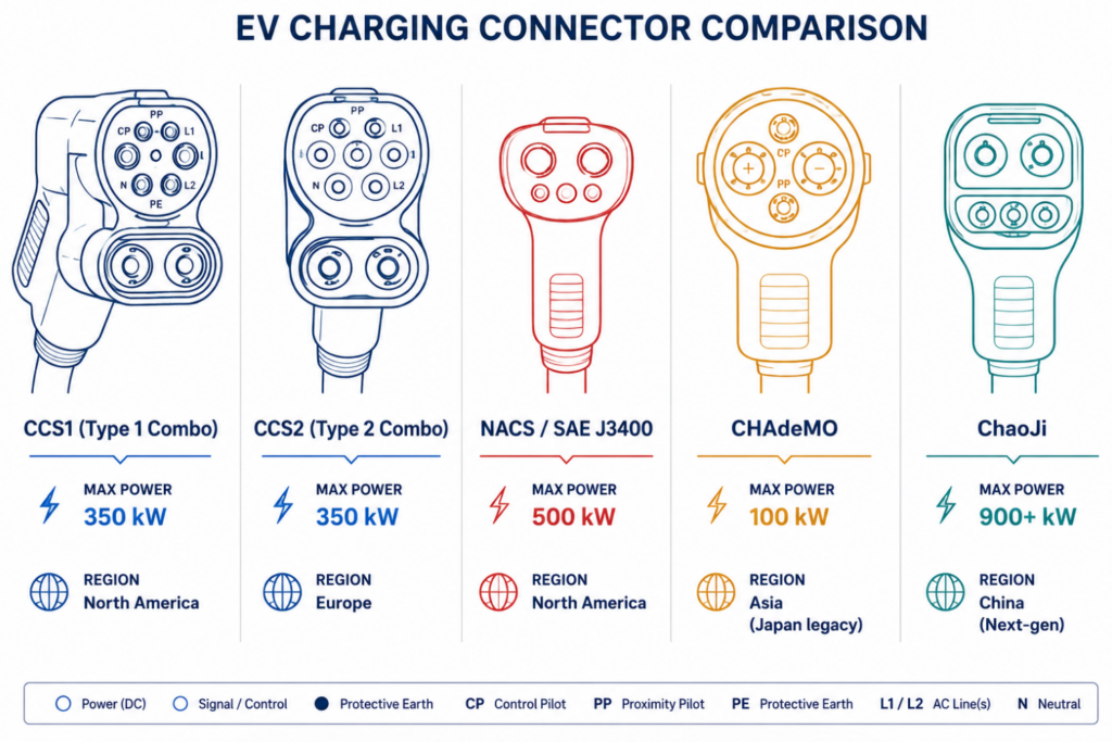
Five distinct connector families serve the DC fast charging market globally. Each originated in different regional or industry ecosystems and carries different electrical specifications, communication protocols, and market trajectories.
| CCS1 & CCS2 | NACS / SAE J3400 | CHAdeMO | GB/T DC | ChaoJi (CHAdeMO 3.0) | |
| Managed by | CharIN / IEC | SAE International | CHAdeMO Association | China Electricity Council | CHAdeMO + China CEC |
| Regions | NA (CCS1), EU/global (CCS2) | North America (expanding) | Japan; declining globally | China (mandatory) | Japan, China (next-gen) |
| Max voltage | 1,000V DC | 1,000V DC | 1,000V DC (ver. 2.0) | GB/T 20234.3 | 1,500V DC |
| Max current | 500A | 500A | 400A (ver. 2.0) | 750V DC (current gen) | 600A |
| Max power | 350–450 kW (deployed)[5] | 500 kW rated; V4 Supercharger 500 kW[6] | 400 kW (ver. 2.0)[3] | 250A (current gen) | 900 kW[7] |
| Communication | ISO 15118 / DIN 70121 | ISO 15118 / PLC via CP pin | CAN bus (proprietary) | ~188 kW (current gen) | New signaling; backward compat via adapter |
| V2G | Via ISO 15118-20 | Via ISO 15118-20 (J3400/2) | Native — V2G from version 1.x | GB/T 27930 (CAN-based) | Full V2G/V2X support |
| Status | Dominant in EU; transitioning in NA | Replacing CCS1 in NA from 2025 MY | Legacy; pivoting to ChaoJi | Mandatory in China; ChaoJi as successor | Specification released 2020; deployment emerging |
Regional Deployment Overview
| Region | Primary DC Standard(s) | Status / Notes |
|---|---|---|
| North America | CCS1 NACS (J3400) | Transition from CCS1 to NACS accelerating; most 2025 MY vehicles ship with native NACS. NEVI program requires CCS connector plus optional NACS. |
| Europe | CCS2 | CCS2 mandated for public DC fast charging by AFIR (Alternative Fuels Infrastructure Regulation). CHAdeMO present but declining in new deployments. |
| China | GB/T DC | GB/T 20234.3 mandatory for all domestic EVs. ChaoJi as future high-power successor. CCS/NACS not deployed domestically. |
| Japan | CHAdeMO | CHAdeMO historically dominant. Industry watching NACS adoption by Stellantis (Japan/Korea models from 2027) and Volvo. ChaoJi development ongoing. |
| South Korea | CCS1 CHAdeMO | Dual-standard market. Hyundai/Kia moving to 800V CCS2-based architecture; NACS adoption possible following Japanese OEM signals. |
| Australia / NZ | CCS2 | CCS2 standard; CHAdeMO declining. NACS/J3400 adoption possible as OEM lineups standardize on NACS. |
| India | CCS2 CHAdeMO GB/T | Multi-standard market; CCS2 gaining traction. BIS (Bureau of Indian Standards) steering toward CCS2 alignment. |
| Middle East / SE Asia | CCS2 NACS (emerging) | Predominantly CCS2 in new deployments. Markets tracking OEM NACS decisions for long-term standard alignment. |
Factors Affecting Actual Charging Speed
The rated power of a DCFC station and the time a driver actually experiences are often different. Actual charging speed is determined by the lowest ceiling across charger, vehicle, and environment.

The DC Fast Charging Curve
A DC fast charging session follows a predictable power profile. Understanding this curve is critical for planning charging stops — particularly the well-known drop-off above 80% SoC.
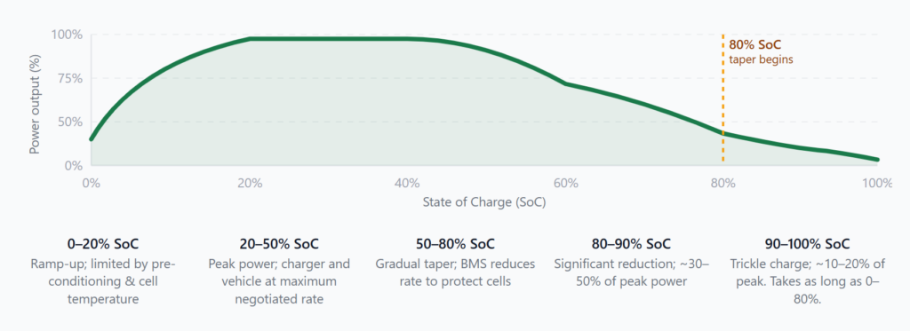
The shape of this curve varies by chemistry. LFP batteries (lithium iron phosphate) have a notably flat discharge voltage curve and can often accept higher charge rates closer to 100% SoC than NMC batteries. NMC batteries have a steeper taper, especially above 80% SoC, to prevent lithium plating and thermal stress. Most charging guidance recommends targeting 80% SoC for DC fast charging stops — the last 20% takes roughly as long as the first 80%.
Many modern EVs (Tesla, Hyundai Ioniq 6, Porsche Taycan, BMW i4, Lucid Air) support battery preconditioning: when navigating to a fast charger, the vehicle’s thermal management system pre-heats or pre-cools the battery to its optimal charging temperature. Preconditioned batteries can accept significantly higher peak power and maintain it for longer — often resulting in 20–40% faster total charge times compared to arriving with a cold battery.
V2G & Bidirectional DC Charging
DC fast chargers are not inherently unidirectional. The power electronics inside a DCFC station — the same that convert AC to DC — can, with appropriate hardware design, reverse the process: converting DC from the vehicle battery back to AC for the grid or building.
This capability, known as Vehicle-to-Grid (V2G) or more broadly Vehicle-to-Everything (V2X), enables EVs to act as mobile energy storage assets. DC-based V2G offers significantly higher power export capacity than AC-based V2G: up to 350+ kW bidirectional via DCFC versus typically 3.7–11 kW via AC V2G.
Requirements for Bidirectional DC Fast Charging
| Requirement | Detail |
|---|---|
| Bidirectional EVSE | The charging station must include bidirectional power conversion hardware (4-quadrant inverter). Most currently deployed DCFC stations are unidirectional. |
| Compatible vehicle | The EV must support V2G at the battery and OBC/DC interface level. V2G-capable vehicles include Nissan Leaf (CHAdeMO V2G), BYD models (GB/T V2G), Hyundai Ioniq 5 N, and select commercial EVs. |
| Communication protocol | ISO 15118-20 (for CCS/NACS/ChaoJi) or CHAdeMO protocol (native V2G from ver. 1.x). ISO 15118-20 support in OCPP 2.1 for network-level V2G dispatch.[8] |
| Grid interconnection | IEEE 1547 (US) or applicable grid code compliance for export; utility agreement often required for commercial V2G participation |
| Aggregation platform | For grid services revenue, V2G-capable chargers require an EMS or DERMS platform to aggregate capacity and respond to grid operator signals (OpenADR, ISO 15118-20 signals) |
Joint’s EVD series DC fast chargers covers 30 kW to 480 kW, including the EVD002 with dual 208V/480V input — a significant advantage for US commercial sites that avoids costly transformer upgrades. All EVD units support OCPP 2.0.1 and ISO 15118-2 (Plug & Charge). The EVD series is certified for both CCS2 (EU) and CCS1 (North America) configurations. JointCharging is preparing ISO 15118-20 support for bidirectional V2G capability in line with OCPP 2.1 deployment timelines. DC fast chargers are deployed alongside BESS in JointCharging’s PV+ESS+EVSE integrated system deployments across Czech Republic, Malaysia, Saudi Arabia, and Georgia.
See Also
- Electric Vehicle Supply Equipment (EVSE)
- CCS (Combined Charging System)
- North American Charging Standard (NACS)
- Battery Energy Storage System (BESS)
- Charge Point Operator (CPO)
Sources & References
- [1] IEC 61851-23: Electric vehicle conductive charging systems — Part 23: DC EV charging stations. International Electrotechnical Commission. Mode 4 definition.
- [2] Joint Office of Energy and Transportation, “NEVI Program Q&A — OCPP 2.0.1 and ISO 15118-2 Plug & Charge requirements.” driveelectric.gov
- [3] CHAdeMO Association, “CHAdeMO Standard and Design — Version History (1.0 → 2.0 → 3.0 / ChaoJi).” chademo.com/technology/high-power; CHAdeMO 2.0: 400A × 1,000V = 400 kW.
- [4] Wikipedia, “Megawatt Charging System (MCS),” CharIN standard: 3,000A × 1,250V = 3.75 MW maximum. wikipedia.org
- [5] CharIN FAQ, “CCS high charging rates of 350 kW+ to enable quick charging.” CharIN also references up to 450 kW in HPC specifications. charin.global/faq-section/
- [6] Wikipedia, “North American Charging Standard,” SAE J3400 maximum power rating 500 kW; Tesla V4 Supercharger delivers up to 500 kW. wikipedia.org
- [7] CHAdeMO Association / Wikipedia, “ChaoJi”: 600A × 1,500V = 900 kW. Released as CHAdeMO 3.0 in April 2020, co-developed with China Electricity Council. wikipedia.org/wiki/ChaoJi
- [8] Open Charge Alliance, “OCPP 2.1 — New functional block on bidirectional charging; ISO 15118-20 support,” released January 23, 2025. openchargealliance.org
