Definition
A Battery Energy Storage System (BESS) is an electrochemical energy storage system that captures electrical energy and stores it in rechargeable batteries for later use. A complete BESS integrates five core subsystems: the battery array (cells, modules, packs), Battery Management System (BMS), Power Conversion System (PCS), thermal management system, and Energy Management System (EMS). BESS is a subset of energy storage technologies — distinct from pumped hydro, compressed air, flywheels, and hydrogen storage. Lithium-ion BESS, particularly LFP chemistry, is the dominant technology in grid-scale and commercial/industrial applications as of 2026.
On This Page
Core Components
A BESS is not a single device — it is a system of interdependent subsystems. Each layer has a distinct function, and the failure of any one subsystem affects the safety and performance of the whole.
| Battery Management System (BMS) | Power Conversion System (PCS) | Thermal Management System | Energy Management System (EMS) | Fire Safety Systems |
| Monitors and protects individual battery cells. Key functions: 1. Cell voltage and temperature monitoring 2. State of Charge (SoC) and State of Health (SoH) estimation 3. Cell balancing (passive or active) 4. Protection: overvoltage, undervoltage, overcurrent, overtemperature 5. Low-temperature charge cutoff (<0°C for LFP to prevent lithium plating) | Converts between AC (grid) and DC (battery) power. Also called the inverter or bidirectional converter. Key parameters: 1. Rated power: kW to MW scale 2. Max efficiency: 95–98.5% 3. DC voltage range: 600–1,500V 4. AC output: 208V to 34.5 kV (utility-scale) 5. Cooling: air, liquid, or hybrid | Maintains battery temperature within the safe operating window. Design choices: 1. Air cooling — lower cost, smaller systems 2. Liquid cooling — higher efficiency, standard in MW-scale BESS 3. HVAC — containerized enclosures 4. Typical operating range: −20°C to +50°C (derated at extremes) | The supervisory control layer. Optimizes BESS operation based on grid signals, energy prices, and local load. Functions: 1. Charge/discharge scheduling 2. Grid service participation (frequency regulation, demand response) 3. Solar generation integration and time-shifting 4. Integration with DERMS for aggregated fleet control | Required by NFPA 855 and fire codes. Typically includes: 1. Gas detection (CO, H₂, electrolyte vapors) 2. Fire suppression (clean agent or water-based) 3. Deflagration venting (NFPA 68) 4. Thermal propagation barriers between modules 5. UL 9540A large-scale fire test data required for installation approval |
")
Battery Cell Hierarchy
Battery systems are built from the smallest electrochemical unit (cell) upward through a structured assembly hierarchy. Understanding this hierarchy is important for interpreting BESS capacity ratings and failure modes.
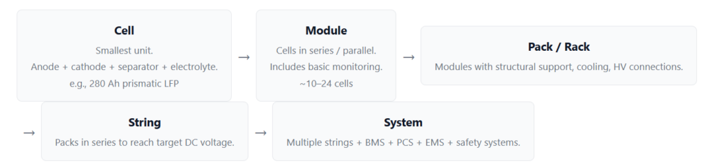
The distinction between cell format types matters for BESS design. Prismatic cells (rigid aluminum casing) are dominant in stationary BESS — the 280 Ah and 304 Ah LFP prismatic cell formats from Chinese manufacturers (CATL, EVE, BYD) have become something of an industry standard for MW-scale systems. Cylindrical cells (18650, 21700) are common in smaller commercial systems. Pouch cells are less common in large BESS due to swelling management complexity.
Battery Chemistries in BESS
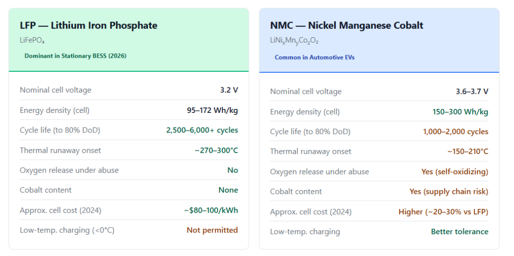
Two lithium-ion chemistries dominate the stationary BESS market: LFP (lithium iron phosphate) and NMC (nickel manganese cobalt). They represent fundamentally different trade-offs between energy density, cycle life, and safety.
Why LFP Dominates Stationary Storage
LFP’s olivine crystal structure uses strong phosphorus-oxygen covalent bonds. Under thermal stress, these bonds do not release oxygen — the key reason LFP does not self-propagate combustion the way NMC does. When an NMC cell enters thermal runaway, the cathode releases oxygen that feeds the exothermic reaction. LFP does not. This is not simply a marketing claim — it is a structural chemistry difference confirmed in peer-reviewed calorimetry studies.[1]
In practical terms: LFP cells begin thermal runaway at ~270–300°C versus ~150–210°C for NMC. Once in runaway, NMC cells reach surface temperatures up to 800°C; LFP peaks at around 620°C. NMC/graphite cells release approximately 20–25 kJ/Ah of energy during thermal runaway; LFP/graphite releases roughly half — 10–15 kJ/Ah.[2]
By 2024, LFP accounted for approximately 70% of global stationary energy storage deployments by chemistry, driven by cost, safety, and cycle life advantages. LFP cell prices fell to approximately $80–100/kWh in 2024, down from ~$150/kWh in 2020 — a ~40% cost reduction in four years.[3]
Comparison Table
| Property | LFP | NMC | Advantage |
|---|---|---|---|
| Nominal cell voltage | 3.2 V | 3.6–3.7 V | NMC (higher voltage) |
| Gravimetric energy density | 95–172 Wh/kg | 150–300 Wh/kg | NMC |
| Cycle life (to 80% capacity) | 2,500–6,000+ cycles | 1,000–2,000 cycles | LFP (3× or more) |
| Thermal runaway onset | ~270–300°C | ~150–210°C | LFP (significantly higher) |
| Oxygen release under abuse | No | Yes (self-oxidizing) | LFP |
| Cobalt supply chain risk | None | Yes | LFP |
| Cell cost (approx. 2024) | ~$80–100/kWh | Higher (~20–30%) | LFP |
| Low-temperature charging | Restricted (<0°C prohibited) | Better tolerance | NMC |
| Primary stationary BESS use | Dominant — grid, C&I, residential | Less common (legacy systems) | LFP |

Technical Specifications
The following table reflects typical specifications for a containerized commercial/industrial BESS in the 1–2.5 MWh class — the most widely deployed format for C&I peak shaving and grid-connected applications in 2026.
| Parameter | Typical Value | Notes |
|---|---|---|
| Rated power | 250 kW – 2,500 kW | Scalable through parallel string configuration |
| Usable energy capacity | 500 kWh – 5 MWh | Per 20-ft container; larger projects stack multiple units |
| Battery chemistry | LFP (dominant) | Prismatic 280–314 Ah cells; NMC in older/legacy systems |
| DC voltage range | 1,000–1,500 V | High-voltage DC architecture reduces current and losses |
| AC voltage (output) | 400–690 V (3-phase) | Stepped up via transformer for grid interconnection |
| Round-trip efficiency (AC-AC) | 85–92% | Includes PCS, BMS, thermal losses; best systems approach 92% |
| Response time | <100 ms (grid-following) <10 ms (grid-forming) | Much faster than gas turbines or hydro; key advantage for frequency regulation |
| Cycle life (system level) | 4,000–6,000 cycles to 80% capacity | Assuming LFP, 80% depth of discharge, optimal temperature |
| Calendar life | 10–15 years | Warranty periods typically 10 years; calendar degradation depends on SoC profile |
| Operating temperature | −20°C to +50°C | Derated at extremes; charging restricted below 0°C for LFP |
| Enclosure rating | IP54–IP65 | IP65 required for outdoor exposure to rain and dust |
| Cooling system | Liquid-cooled (modern systems) | Air-cooled HVAC in older designs; liquid cooling increasingly standard for >500 kWh |
| Communication protocols | Modbus TCP, DNP3, IEC 61850, CAN | EMS integration; IEC 61850 for utility-grade grid interconnection |
Applications
BESS serves different roles depending on where it connects in the energy system — at the transmission level, in energy markets, or at the distribution and behind-the-meter level.
| Grid — Transmission Level | Grid — Transmission Level | Market — Energy Arbitrage | Market — Energy Arbitrage | Behind-the-Meter — C&I | Behind-the-Meter — EVSE | Resilience | Grid — Distribution |
| Frequency Regulation | Synthetic Inertia | Renewable Integration | Price Arbitrage | Peak Shaving | EV Charging Buffer | Backup Power | Distribution Support |
| Maintains grid frequency (60 Hz / 50 Hz) by injecting or absorbing power within milliseconds. BESS response is far faster than gas turbine peakers or hydro. | Grid-forming inverters emulate the rotational inertia of synchronous generators, stabilizing frequency without spinning mass. Critical as coal and gas plants retire. | Stores solar or wind generation during surplus (midday, high-wind periods) and dispatches during evening demand peaks — converting intermittent to dispatchable power. | Charges during low-price hours (off-peak, negative pricing during solar glut) and discharges during peak pricing. Revenue depends on price spread and round-trip efficiency. | Reduces a facility’s peak demand draw, lowering demand charges on utility bills. High ROI in markets with significant demand charge components ($/kW/month). | Absorbs the peak load from DC fast chargers, enabling high-power EV charging without expensive grid connection upgrades. See Relationship to EV Charging. | Provides uninterrupted power during grid outages. Combined with solar, enables extended island-mode operation for critical facilities. | Reduces distribution circuit overload, increases renewable hosting capacity, and defers or eliminates costly distribution infrastructure upgrades. |
Grid Services and Market Participation
BESS can provide multiple services simultaneously to grid operators, a concept known as value stacking. Faster response time is one of the primary advantages of battery storage over conventional generation assets.
| Service | Description | Response Time | Duration |
|---|---|---|---|
| Primary Frequency Response (FCR) | Automatic response to frequency deviations; maintains grid stability | <2 seconds | 30 seconds – 30 minutes |
| Secondary Frequency Regulation (FRR) | Slower automatic generation control; restores frequency to setpoint | <30 seconds | Minutes to hours |
| Voltage Support | Reactive power injection or absorption to maintain voltage levels | <1 second | Continuous |
| Spinning Reserve | Backup capacity held ready for sudden generation loss | <10 minutes | Up to 2 hours |
| Ramp Rate Control | Smooths solar/wind output variability to meet grid ramp rate limits | Seconds | Continuous |
| Black Start | Restarts a grid section after total outage without external power | Islanded operation | Until grid restored |
| Synthetic Inertia | Grid-forming inverters emulate rotational inertia of synchronous generators | <100 ms | Seconds |
A gas turbine peaker plant typically takes 10–30 minutes to reach full output from cold start. A BESS can reach full rated power in under 100 milliseconds. This speed advantage is why BESS has captured a disproportionate share of frequency regulation markets in regions where those markets price on response speed (US PJM, UK, Australian NEM).
Safety Standards and Codes
BESS installations must navigate a layered set of standards — some governing the product itself (listing standards), some governing testing methodology (test methods), and some governing how and where BESS can be installed (installation codes). These are distinct categories and should not be confused.
United States — Installation Codes
| Standard | Type | Scope |
|---|---|---|
| NFPA 855 (2026 Edition) | Installation Code | The primary installation standard for stationary ESS in the US. Covers siting, separation distances, fire protection requirements, hazard mitigation analysis (HMA), and now mandates large-scale fire test data for installation approval |
| International Fire Code (IFC) / NFPA 1 | Fire Code | Adopted by most US jurisdictions; includes ESS-specific provisions that reference NFPA 855 and UL 9540 |
| NFPA 70 (NEC) | Electrical Code | Article 706 covers ESS electrical installation requirements: wiring, disconnects, overcurrent protection, grounding |
| NFPA 68 | Fire Code | Deflagration venting design — required for BESS enclosures where flammable gas accumulation is possible |
| NFPA 69 | Fire Code | Explosion prevention systems — inert gas suppression and related measures |
Product Safety and Test Standards
| Standard | Type | Scope |
|---|---|---|
| UL 9540 | Listing Standard | Safety listing standard for the complete ESS. Required by most US fire codes for any BESS installation. Covers the integrated system (batteries, BMS, PCS, enclosure) as a listed product |
| UL 9540A (6th Edition, Mar 13, 2026) | Test Method Updated 2026 | The primary fire propagation test method for BESS — not a listing standard but a test methodology. Generates data used by NFPA 855 and IFC for installation approval, spacing decisions, and HMA. The 6th Edition significantly revises large-scale fire testing to align with NFPA 855 Annex G.11. Effective date for new installations: January 1, 2027.[4] |
| UL 1973 | Listing Standard | Batteries for stationary, vehicle propulsion auxiliary power applications — component-level standard for battery packs within a BESS |
| UL 1642 | Listing Standard | Lithium battery component safety — applies to individual lithium cells used in larger systems |
Published March 13, 2026, the 6th Edition of UL 9540A introduced significantly stronger requirements for large-scale fire testing of BESS. The key revision: Section 10 now incorporates a clear large-scale fire test method that aligns directly with NFPA 855 Annex G.11’s requirements. This edition also extends applicability to alternative chemistries (sodium-ion) and improves reproducibility of test results. The effective date for new installation approvals is January 1, 2027.[4][5]
UL 9540A is a test method, not a certification. A BESS that has been “UL 9540A tested” has undergone fire propagation testing that generates data for code compliance — it is not the same as being listed to UL 9540. Both are typically required: UL 9540 listing for the product, UL 9540A test data for the installation permit. Authorities Having Jurisdiction (AHJs) frequently require both during plan review.
International Standards
| Standard | Scope |
|---|---|
| IEC 62933 | Electrical Energy Storage (EES) Systems series — overall framework covering terminology, performance, and safety for grid-connected BESS |
| IEC 62619 | Safety requirements for secondary lithium cells and batteries for use in industrial applications — cell-level standard |
| IEEE 1547 | Standard for interconnection and interoperability of distributed energy resources (DERs) with the electric power system — governs BESS grid connection requirements in the US |
| IEC 61850 | Communication standard for electrical substations and DERs — commonly used for BESS-to-grid communications in utility-scale deployments |
Relationship to EV Charging
BESS and EV charging infrastructure are increasingly co-deployed, addressing a fundamental problem: DC fast charging demands large amounts of power in short, unpredictable bursts — exactly the kind of load profile that stresses grid connections and drives up demand charges.
Why BESS and EVSE Are Paired
| Use Case | Problem Solved | How BESS Helps |
|---|---|---|
| Peak demand at DC fast charging sites | Each 150 kW DCFC draws 150 kW instantaneously; 4-port site = potential 600 kW peak | BESS buffers peak draw, keeping site demand below grid connection threshold |
| Demand charge reduction | Demand charges can add $15–$25/kW/month — $2,250–$3,750/month for a 150 kW peak | BESS discharge during peak windows prevents demand charge triggers |
| Grid connection cost avoidance | Upgrading from a 200A to 400A service can cost $50,000–$500,000 depending on location | BESS enables high-power EVSE on existing grid connections that would otherwise require upgrade |
| Solar self-consumption | Rooftop solar generates midday; EV charging demand peaks evenings | BESS stores solar surplus and dispatches for evening EV sessions |
| V2G aggregation | Vehicle batteries are underutilized assets for most of the day | BESS + V2G-capable EVSE aggregates vehicle battery capacity as dispatchable grid storage |
The integration of solar generation, battery storage, and EV charging into a single coordinated system is known as a PV+ESS+EVSE deployment. These integrated systems require an EMS that can simultaneously optimize solar self-consumption, grid import costs, EV charging demand, and battery state of charge — a significantly more complex control problem than any single component alone.
Joint ‘s R-ESS (Residential Energy Storage System) is designed for integrated PV+ESS+EVSE deployments, including large-scale residential community projects. JointCharging has deployed integrated PV+ESS+EVSE systems across Czech Republic (6,000 residential units), Malaysia, Saudi Arabia, and Georgia. The AI-based EMS in these deployments provides minute-level solar forecasting and dynamic BESS dispatch coordination with EVSE load management.

See Also
- EVSE (Electric Vehicle Supply Equipment)
- OCPP (Communication Protocol)
- V2G (Vehicle-to-Grid)
- CPO (Charge Point Operator)
Sources & References
- [1] Electric & Hybrid Vehicle Technology International, “LFP vs NMC Thermal Runaway,” March 2025. electrichybridvehicletechnology.com; ACS Energy Letters, “Evaluating Fire and Smoke Risks with Lithium-Ion Cells,” 2024. pubs.acs.org
- [2] Battery Design, “Objective Safety Analysis of NMC vs LFP,” February 2026. batterydesign.net
- [3] GlobalSpec Electronics360, “From NMC to LFP Batteries,” November 2025. electronics360.globalspec.com; IDTechEx, “Iron and Phosphate to Unlock the Mass-Market EV,” January 2025. idtechex.com
- [4] UL Solutions, “Installation Codes and Requirements for Energy Storage Systems — FAQs,” published March 13, 2026. ul.com; Intertek, “Advancing Fire Safety in Energy Storage: Understanding the 2026 Update to UL 9540A,” March 23, 2026. intertek.com
- [5] UL Solutions, “UL 9540A Test Method for Battery Energy Storage Systems.” ul.com/services/ul-9540a-test-method; Energy-Storage.news, “UL9540A: New Edition Establishes New Precedent,” March 17, 2026. energy-storage.news
- [6] Wikipedia, “Lithium Iron Phosphate Battery,” citing cell-level energy density 95–172 Wh/kg; CATL cell-level claim 205 Wh/kg (2024). wikipedia.org
